BrickVista Logo BrickVista Flowers
Flowers Flowers Flowers Flowers
           Home  Models  Themes  Features  Links
   YogiCub  M.O.P Rover
     
    MTM - Mobility / Syspension Design


The Mobility system of the M.O.P Rover comprises of four elements.

1   The Drive Actuators
The motors that propel the Rover
2   Drive Assembly
How power is transferred from the motors to the wheels
3   Steering
How the Rover physically orientates it’s self within its environment
4  

Suspension
How Rover weight is dispersed through to the ground


Lets look at how the M.O.P Chassis addresses each of these areas.


1  

Yellow ZoneDrive Actuators
As 
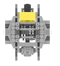
we learnt earlier the M.O.P Chassis is divided into three zones. The Drive Actuators (motors) are located in the Yellow Zone (Motor Bay). They provide drive to the wheels via a drive assembly (Located in the Red Zone)

While this may not seem the most efficient way to power the wheels (See YogiCub for an alternative method) it does allow us to modify each part of the Mobility system independently without having to re-design the whole rover.

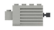
The most common drive motors used in mobile LEGO Rovers (and many other applications) are the 9V Technic Mini-Motor. These little beauties have internal gearing and are very efficent when powered from the RCX – They are an ideal choice for an all round drive motor. However there are many other types of LEGO motor available, and luckly for us, the Motor bay allows for different motor fixing methods.
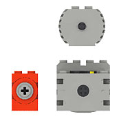
The older LEGO 9V Technic motor,or the newer transparent Geared Motor, would be the most obvious alternatives, each having specific perfmance characteristics however it is not inconceivable to mount a RC Race Buggy motor into the chassis (as long as it had a tethered power supply).

Check out Philippe Hurbain’s massive motor comparison to see what each motor has going for it.


MOTOR SPEED

9V Motor

No two electric motors have the same efficiency. When comparing motor one will always spin a little faster, or slower than the other. In some motors this variation can differ up to 12%. Meaning one motor might turn at 200RMP, and the other at 224RMP. This might not seem a problem until you place each motor into a drive train to power your wheels. The result means that each wheel will turn at a slightly different speeds. Your Rover will ALWAYS veer off-course and never drive straight.

To overcome this you could
use matched motors with similar RPM. Have the RCX monitor both outputs (RPM) and trim power to each motor as required. Use a differential in an "adder" configuration to average the outputs of the motors. Drive all your wheels through a single drive train.


Each solution has its advantages and limitations. Both Steve Baker and Philippe Hurbain have carried out extensive testing of the performance of LEGO® motors


Steve Baker’s
Motor – Mismatch

Philippe Hurbain’s
Motor comparison


  Previous  Page 1 Page 2 Page 3 Page 4 Page 5 Page 6 Page 7 Page 8 Page 9Page 10 Page 11 Page 12 Page 13 Page 14 Page 15 Page 16 Page 17 Page 18 Page 19 Page 20  Next
                                                       
 
 About Us  Site Index  Legal Info  Contact